RF Explorer Configuration Options
Display options
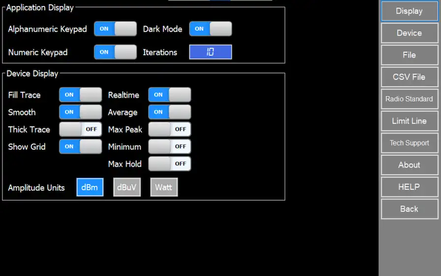
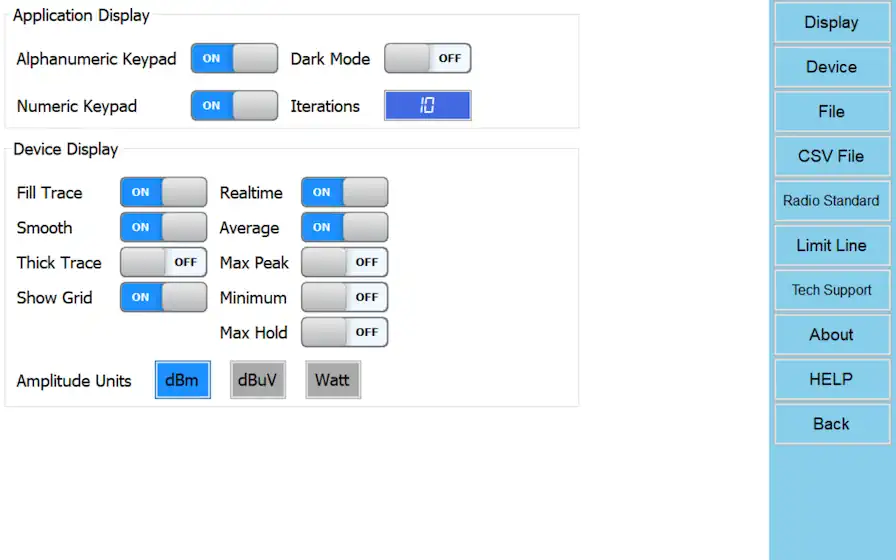
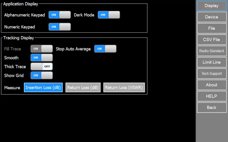
Application Display
Alphanumeric Keypad
Define preference to use a virtual alphanumeric keyboard.
Note if disabled user must display system keypad manually every time to type text.
Numeric Keypad
Define preference to use a virtual numeric keyboard, useful in touch capable tablets and laptops. Note Frequency and Amplitude numeric dialogs are always active.
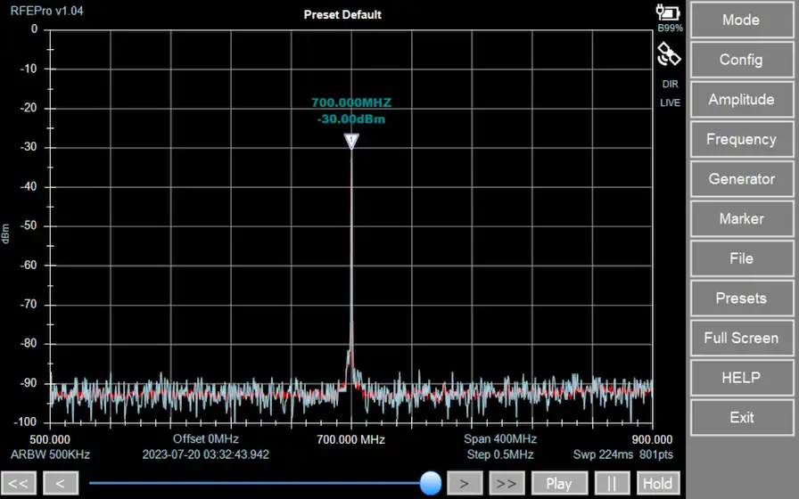
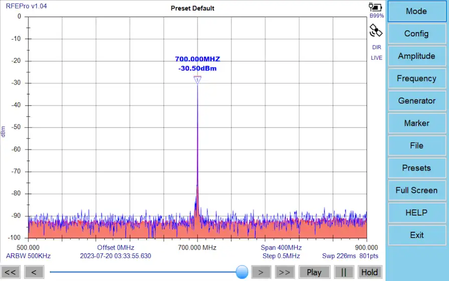
Dark Mode
Set a black background skin, closer to desktop instruments and easier to read in certain environments.
Iterations
The number of sweep data iterations to perform calculations on including Average and MaxPeak (not available for Tracking SNA mode).
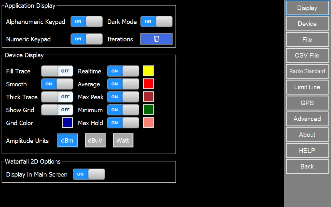
Device Display
Fill Trace
Display a filled area in all signal shapes except Realtime signal.
Smooth
Use soft splines to join data sweep points in order to present a calculated soft curve
Thick Trace
Display trace with extra width
Show Grid
Show grid inside spectrum analyzer graph
Amplitude Units
Select amplitude units between dBm, dBµV or Watt to display data in analyzer graph.
Waterfall 2D Options
Display in Main Screen
Display waterfall spectrogram in main screen together with the spectrum analyzer graph
Note
Waterfall 2D view is only available for Spectrum Analyzer or Frequency Coordination modes
Realtime
Raw data as captured with no post-processing.
Average
Arithmetic media of all the last iterations sampled.
Max Peak
Maximum value of all the last iterations sampled.
Max Hold
Maximum value of all captured samples regardless Iterations value.
Minimum
Minimum value of all the last iterations sampled.
Note
There are modes where trace visualization is restricted by its own specific captured data type and it is not possible to choose the trace to display on the graph in “Device Display” options, as described below:
• Wifi Analyzer – Max Peak trace
• Power Meter – Real Time trace (RF Explorer Pro model)
• Zero Span – Real Time trace (RF Explorer Pro model)
Tracking Display
Stop Auto Average
Automatically stop SNA tracking after <Average> specified number of sweeps
Insertion Loss (dB)
Evaluate signal insertion loss in dB
Return Loss (dB)
Evaluate the ratio of the reflected power to the incident power in dB
Return loss (VSWR)
Evaluate the ratio of the maximum to minimum voltage on a loss-less transmission line
Device options
For more details about RF Explorer Pro device configuration options, please visit:
For more details about RF Explorer Handheld device configuration options, please visit:
Files
File Options
Save RFE Data File on Close
Save a RFE data file every time application is closed. If “Enable Continuous Log” option is enabled, this feature will be enabled automatically.
Continuous log
Enable
Enable continuous log to save RFE data or CSV files periodically in seconds as selected in “Auto Save Delay (s)” option. Also this option save a RFE data file in each configuration change in device and when application is closed.
Auto Save RFE Data
If “Enable” option checked, save a RFE data file every number of seconds selected in “Auto Save Delay (s)” option.
Auto Save CSV
If “Enable” option checked, save a CSV data file every number of seconds selected in “Auto Save Delay (s)” option.
Auto Save Delay (s)
Number of second for Auto-Save feature.
Auto Delete (Days)
Number of days for Auto-Delete old and unused files in user folder
Auto Save Folder
Auto Save Folder Path
Directory where .RFE and CSV files will be stored if Auto Save feature is active
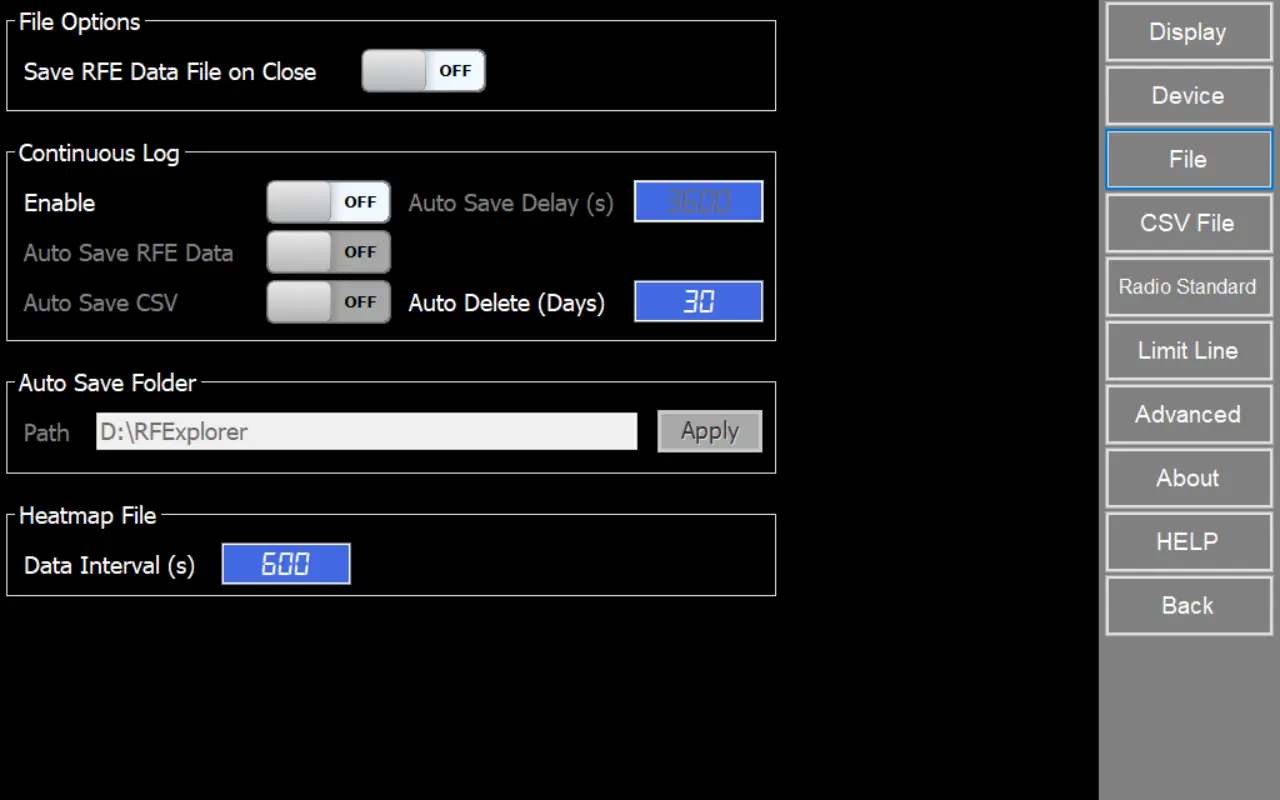
Heatmap File
Data Interval (s)
Specifies the time interval, in seconds, at which a single sweep sample is taken from the entire data collection. Use this setting to control how frequently measurements are recorded to display it in heatmap file.
Note
For RF Explorer Pro model, by default files are stored in USB removable drive if available, otherwise the target directory will be “MyDocuments\RFExplorer”.
The Contiuous Log feature is available for Spectrum Analyzer and Frequency Coordination modes
CSV Files
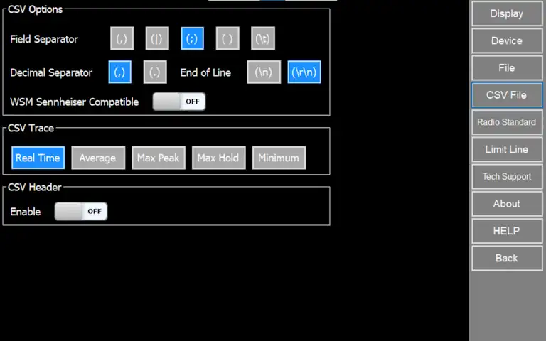
CSV Options
Field Separator
Delimiter to use for CSV file generation.
Supported separators: Comma, Division, Semicolon, Space or Tabulator.
Decimal Separator
Delimiter to use as decimal separator.
Supported separators: Comma or Dot.
End of Line
End of line to use in for CSV file generation.
Supported end of lines: Line Feed (\n) or Carriage Return and Line Feed (\r\n).
WSM Sennheiser Compatible
When option is checked, CSV files generated can be imported directly in WSM Sennheiser software.
CSV Trace
CSV Header
Insert descriptive header inside generated CSV files.
Fields included are:
- Receiver
- Date/Time
- RFUnit
- Owner
- ScanCountry
- CRC
Important
Amplitude data stored in CSV files is always defined in dBm units.
The selected trace must be visible in the graph, if there are multiple visible the tool will select one by this priority order:
1. Average trace
2. Max Peak trace
3. Real Time trace
4. Max Hold trace
5. Minimum trace
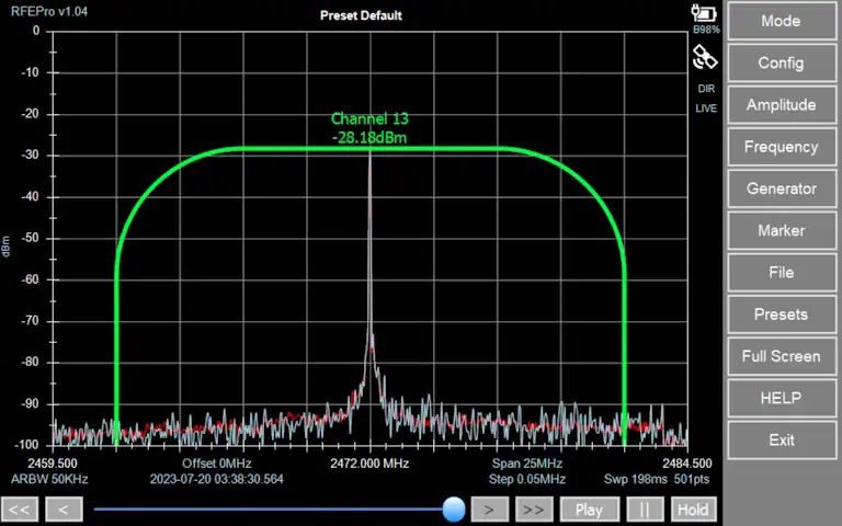
Radio Standards
Feature custom definition of Radio Standard channels.
You can now import standards or define your own channels to be included in the Spectrum Analyzer graph.
Each channel in a Radio Standard will display:
Channel name
Visual shape of the actual bandwidth and channel position
Computed individual power channel
Note
On the first run, the software imports the default Radio Standards so you start with a ready-to-use library.
The software also auto-loads any Radio Standard files found on disk (*.rfersx) and adds them to the inventory when the app starts or when you click [System].
Inventory
Table of available radio standards and related configuration.
Each row is one radio standard (example: WiFi 5GHz). Click a row to select it. The selected row is highlighted. Use the scroll bar on the right of the table to view more items.
Name
Displays the standard name as it will appear across the software (lists, selectors, overlays).
Enable
Turns the standard on or off for use in the application.
- Yes: The standard is available in selectors and can be used for channel lists/overlays.
- No: The standard is hidden or unavailable where standards are used.
Channels
Shows how many channels are defined for that standard.
This is useful to confirm the standard includes the expected channel plan.
Style
Controls how the standard is drawn when shown as an overlay or reference on the spectrum display.
- Solid: Continuous line (best for general use).
- Dashes: Repeating dash segments (easy to spot over busy traces).
- Dotted: Small dot pattern (subtle, low-visual-impact reference).
- DashDot: Alternating dash and dot (distinct when multiple overlays are shown).
Background
Controls whether the overlay uses a filled background behind the standard/channel shapes.
- Yes: Filled background (better visibility on noisy traces).
- No: Outline-only (less visual obstruction).
Border
Controls the outline type of the overlay.
- Rounded: Rounded corners (smooth, readable blocks).
- Bell: Bell-shaped profile (curved “bump” style outline).
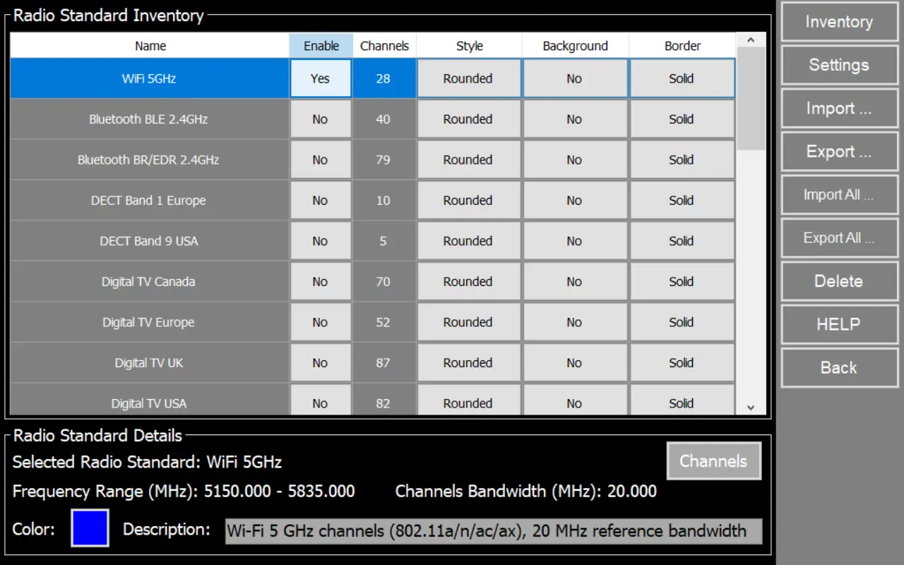
Details
This section shows the parameters of the currently selected row.
Selected Radio Standard
Confirms which table entry you are viewing/editing.
Frequency Range (MHz)
Shows the full frequency coverage of the standard in MHz (start to stop).
Channels Bandwidth (MHz)
Shows the reference channel bandwidth used by the radio standard.
If the channels have different bandwidths, it will be marked as “Mixed.”
Color
Shows the overlay color used to draw the standard.
Tip: Choose a color that contrasts with your trace and grid for easy reading.
Description
Brief explanation of the standard and any notes
Channels
This window shows (and lets you define) the channel inventory for a selected Radio Standard.
Channel Inventory
The table lists all channels included in the current Radio Standard and related frequency configuration defined.
Radio Standard Name
Shows the standard currently being edited.
Channels Start Freq (MHz)
Start frequency used to generate channels when you add them in bulk.
Channels Distance (MHz)
Frequency step between consecutive channels when bulk-generating channels.
Channels Bandwidth (MHz)
Bandwidth assigned to newly added channels.
Total Channels
Shows the total number of channels currently defined for this standard.
Channels to add
Sets how many channels will be added or removed at once.
Add Channels
Adds the specified number of channels using. New channels are appended to the inventory and appear in the table.
Remove Channels
Removes the selected channels from the inventory.
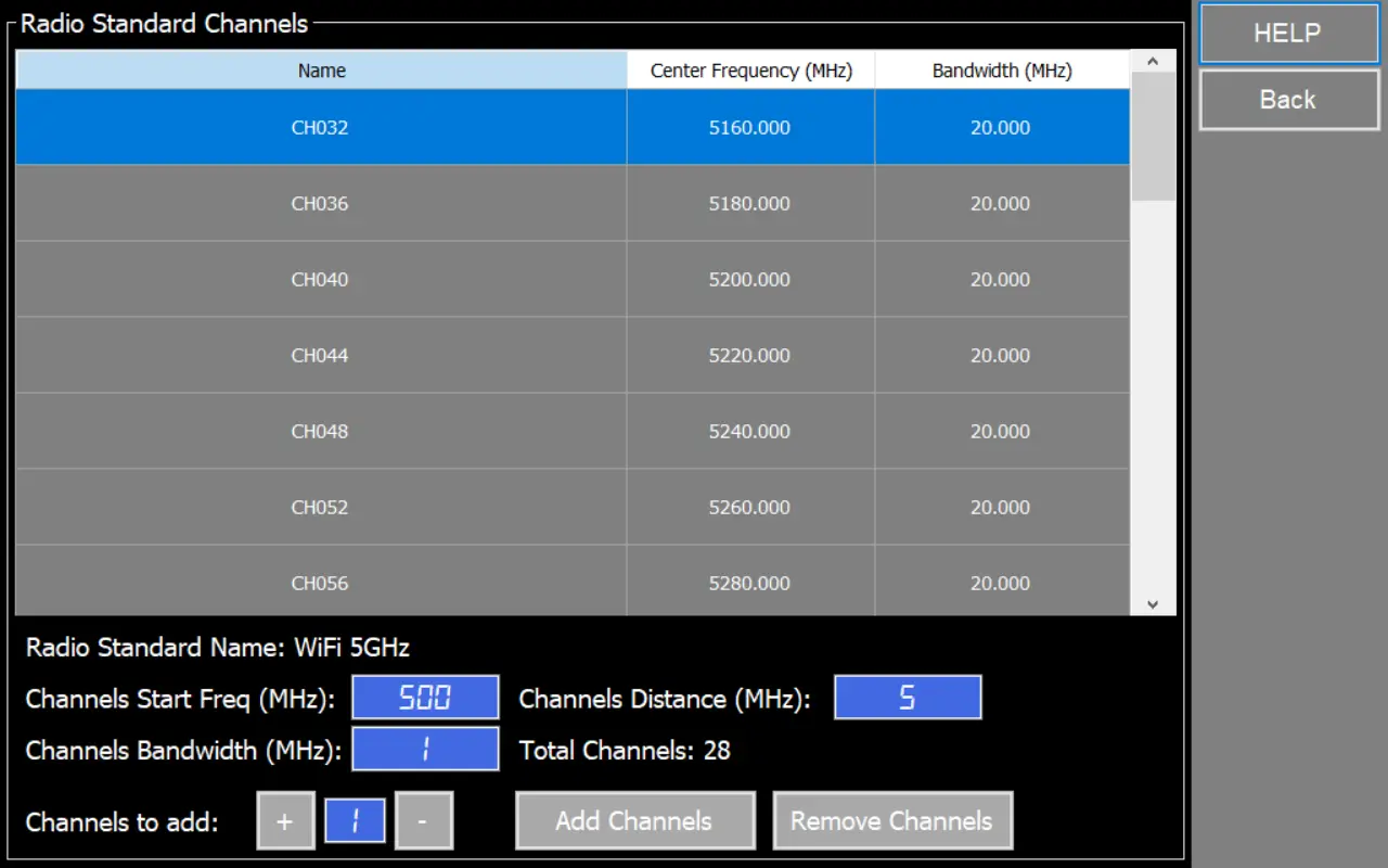
How to add channels to a Radio Standard
Open Radio Standard Inventory.
Select the Radio Standard you want to edit.
Click Channels to open the Radio Standard Channels window.
In Channels Start Freq (MHz), enter the start frequency for the first new channel center.
In Channels Distance (MHz), enter the spacing between channel centers (step).
In Channels Bandwidth (MHz), enter the bandwidth to assign to the new channels.
In Channels to add, set how many channels you want to create
Click Add Channels.
Verify the new channels appear in the table and check Name, Center Frequency (MHz), and Bandwidth (MHz).
File format (*.rfers)
- The first line must contain the header --RFERD01.
- Optionally, additional details about the Radio Standard can be added as comments, prefixed with --.
- Define the Radio Standard Name, displayed in graph.
- Specify the number of channels, which must match the channels listed below.
- Define the Channel Bandwidth (MHz), a single value shared by all channels.
- For each channel, specify its name and center frequency (MHz), ensuring the total number of channels matches the previously defined value.
These files are text files you can edit or create with the tool of your choice (e.g. notepad – although we recommend some better editor such as Notepad++)
File format (*.rfersx)
- XML file (UTF-8).
- More structured and easier to validate programmatically.
- Designed for richer channel definitions.
Key characteristics
- Each channel can have its own bandwidth.
- You can mix channels with different bandwidths in the same standard (for example 5/10/20/40 MHz).
- More fields can be added in a controlled way in future versions (without breaking the layout).
Advantages of .rfersx
- Variable channel bandwidths within the same Radio Standard.
- More readable structure for large standards (XML hierarchy instead of long text blocks).
- Less error-prone imports:
- Channel fields are explicit (Name / CenterMHZ / BandwidthMHZ) and don’t depend on line order as much as text files.
- Better for automation:
- Easier to generate and parse with tools/scripts that already handle XML.
- Go to Config menu.
- Select Radio Standard option.
- Open Inventory.
- In Radio Standard Inventory, click the Radio Standard you want to use.
- In the Enable column, set it to Yes.
- Configure display options Style, Background and Border
")
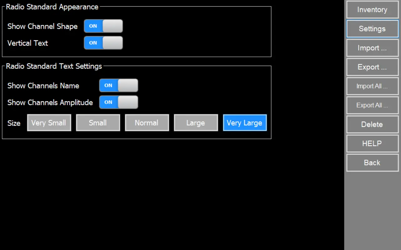
Settings Options
On this screen you control how Radio Standard channels are drawn and labeled on the Spectrum Analyzer graph. These settings affect the channel overlay visibility and text readability.
Radio Standard Appearance
Use these options to change the channel overlay shape and orientation.
Show Channel Shape
- ON: Draws the channel shape/outline for each channel on the graph.
- OFF: Hides the channel shapes. (Text labels may still be shown if enabled below.)
Vertical Text
- ON: Rotates channel text so it reads vertically on the graph.
- OFF: Shows channel text horizontally.
Radio Standard Text Settings
Use these options to control which channel labels are shown and how large they are.
Show Channels Name
- ON: Displays the channel name label (example: CH 36).
- OFF: Hides channel name labels.
Show Channels Amplitude
- ON: Displays a channel amplitude label near each channel (based on the channel power/amplitude computed by the software).
- OFF: Hides channel amplitude labels.
Size
Controls the text size used for channel labels on the graph.
Options: Very Small, Small, Normal, Large and Very Large
Limit Lines
An advanced and powerful tool in the spectrum analyzer mode is the ability to work with Minimum and Maximum Limit Lines.
These are fully configurable, visual and optionally audible alarm feature with multi-data point lines to determine power limits.
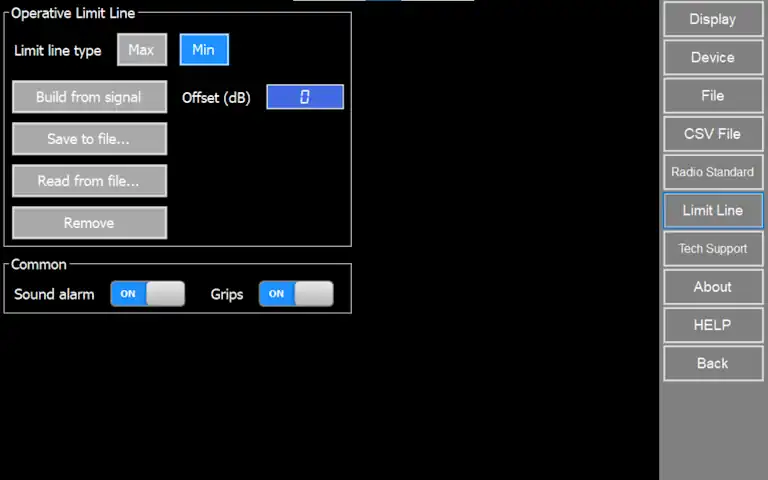
Operative Limit Line
Limit Lines are fixed thresholds, and only one pair of Max / Min limit lines can be specified at any given time.
These settings apply to one limit line type at a time: maximum or minimum. Use to define or change parameters of each limit line as required.
Different limit lines can be loaded from file or generated from a signal trace anytime.
Limit line type
- Max: select to apply changes to maximum limit line.
- Min: select to apply changes to minimum limit line.
Build from signal
Generate maximum or minimum limit line from a currently selected signal trace specifying a positive offset in dB. This offset will be added or subtracted depending on limit line type selected
Save to file
Save maximum or minimum limit line to a limit line file (.rfl).
Read from file
Load maximum or minimum limit line from a limit line file (.rfl).
Remove
Remove maximum or minimum limit line from spectrum analyzer screen.
Common
These settings apply in common to both maximum and minimum limit line
Sound alarm
To enable or disable an audio alarm for as long as the condition is not met
Grips
To enable or disable circle gripped in limit line traces. For high resolution mode, circles might make it hard to see how close limit line trace from signal trace is.
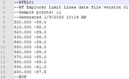
File format
These files are text files you can edit or create with the tool of your choice (e.g. notepad – although we recommend some better editor such as Notepad++)
GPS
RF Explorer Pro
GPS feature is only available for RF Explorer Pro device, for more details visit:
Advanced
Technical Support
Create a compressed ZIP file with activity logs, configuration files and report files in order to diagnose application issues. Only required if requested by RF Explorer Tech Support.
Factory Default
Restore system configuration setting to Factory Default values. Licenses will be preserved, but Presets and other preference settings will be lost.
Note
This action cannot be undone.
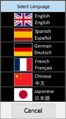
Language
The application includes a Language Options feature that allows users to change the interface language according to their preference.
Multilanguage support for English (EN), Spanish (ES), German (DE), French (FR), Japanese (JA), and Chinese (CH).
This improves usability for international teams and helps reduce mistakes in operational environments where technicians work in different languages.
Note
Language selection will be requested for confirmation the first time you upgrade only.
Diagnostic Report
This function generates a comprehensive PDF document that contains:
• System information: hardware details, firmware version, and operating status.
• Configuration settings: current application parameters and user-defined options.
This report can be shared with technical support to facilitate faster issue resolution or stored as a reference for maintenance and audits.

How to change application appearance